Why Tilt and Turn Windows Break the Nailing-Fin Assumption
Most U.S. installation crews learn residential window installation on products with an integral nailing fin. European-style tilt and turn windows often use a different structural attachment strategy, so treating them like a conventional flanged window can create operational, drainage, and warranty problems.
Key takeaway: A tilt and turn window must be installed as a bracket-supported, hardware-driven system. The rough opening, shimming, cross-blocking, flashing, drainage path, and fastener locations all affect how the sash operates and how the assembly manages water.
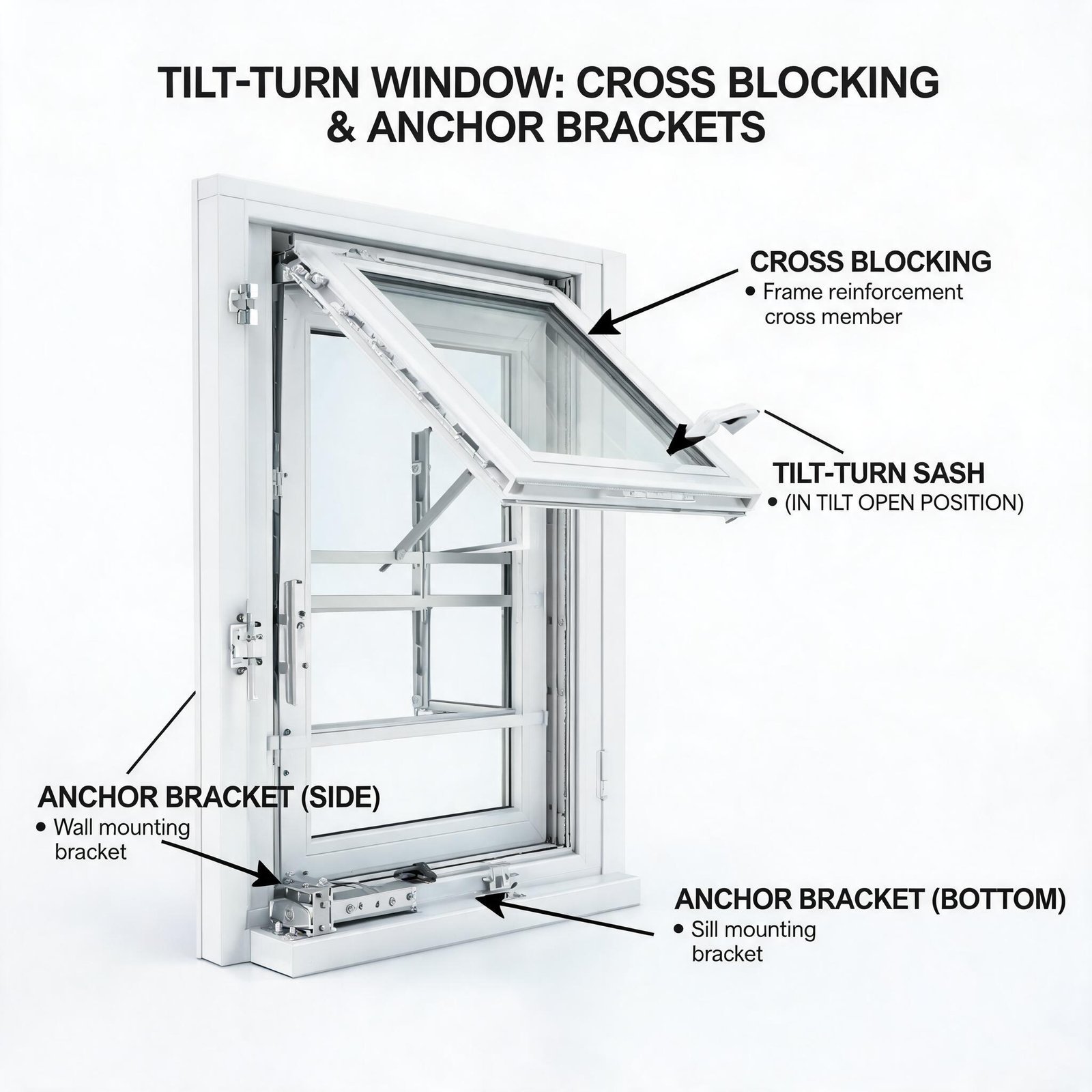
- The anchor-bracket system transfers loads to the framing through adjustable steel brackets, not a continuous flange.
- The hinge-side scissor arm carries the full sash weight in the tilt position and needs solid bearing at the bottom.
- Multi-point locking hardware on the lock jamb creates concentrated compression points that pull the frame square when engaged.
The hardware family is the same one found in modern European tilt and turn door systems, which means the frame is engineered to handle point loads, not flange loads.
Following a generic nailing-fin AAMA 2400 method without accounting for these bearing locations can result in stiff operation, seasonal settlement, sash misalignment, or water intrusion at corners. Always use the window manufacturer’s current installation instructions when they differ from a general installation standard.
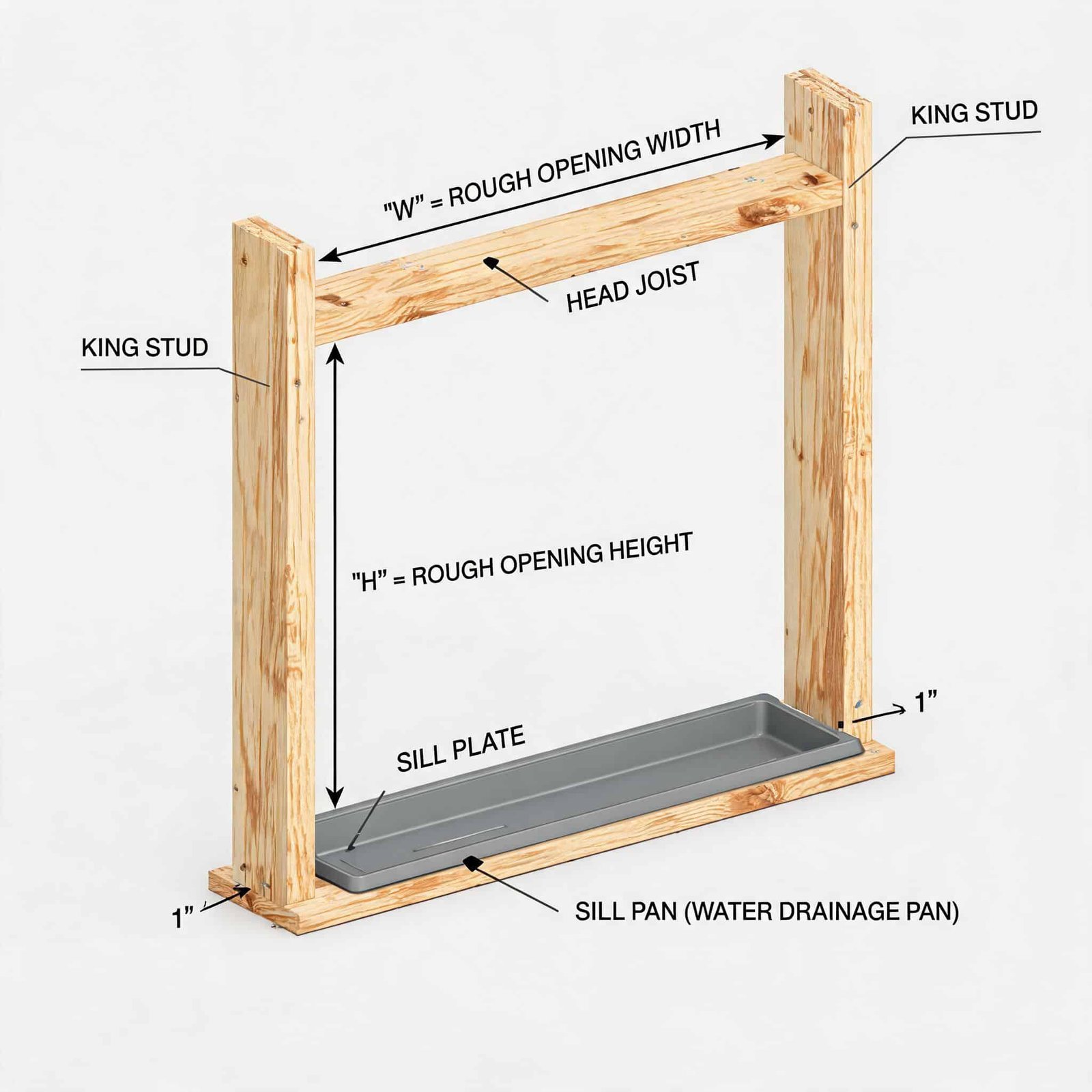
Rough Opening Prep: Framing Tolerances and Backing Support
AAMA 2400 and ASTM E2112 emphasize the same fundamental principle: the framed opening must be plumb, level, square, and true before installation begins. A commonly used field tolerance is no more than 1/4 inch out of plumb, level, square, or true, but the manufacturer’s published tolerance should govern. Check opening width, height, sill level, jamb plumb, and both diagonal measurements before setting the window.
Sill framing must be straight and level. A bowed, crowned, or twisted sill member can distort the window sill, alter drainage, and bind the sash or multi-point locking hardware.
The Backing Support Requirement Most Crews Miss
If you plan to apply self-adhered flashing directly over wood framing, AAMA 2400’s addendum requires a flat backing support to be installed first. That backing gets applied before the building wrap, and then the mounting flange or anchor brackets sit flush against it.
Skip the backing support, and the flashing can bridge voids, telegraph framing imperfections, and lose adhesion at exactly the points where water collects. Flat, continuous backing also helps maintain a reliable drainage plane behind exterior cladding.
Fastener Specifications That Actually Hold
- Use screws only for anchor-bracket tilt-turn units: #8 pan-head screws or better, penetrating at least 1 inch into framing.
- Space fasteners no more than 4 inches from bracket corners.
- 6D nails are acceptable for flanged windows in wood framing, but they will not resist the cyclic loads of a tilt-turn mechanism.
Fastener type, embedment, corrosion resistance, and spacing should match the window manufacturer’s instructions and the project design pressure requirements. Do not substitute staples or nails where the bracket schedule specifies screws.
AAMA 2400 Flashing Sequence: Two Methods, One Weatherboard Rule
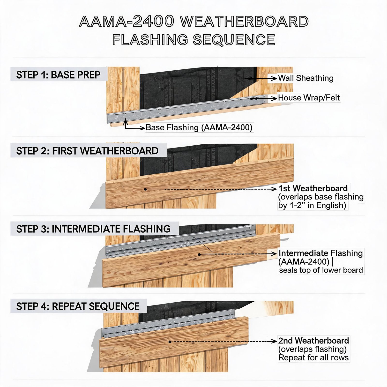
What is the AAMA 2400 flashing sequence? The order is weatherboard style: sill first, then jambs, then head. Every subsequent layer overlaps the one below it, creating a shingle-style drainage path that directs incidental water outward rather than behind the weather-resistive barrier (WRB).
Method A — Flashing Over the Face of the Mounting Flange
- Apply the sill strip first, cut to the width of the window opening plus twice the width of the jamb flashing.
- Install vertical jamb flashings so their edges align exactly with the sill flashing — no exposed transitions.
- Run the head flashing across the top, extending at least 1 inch beyond the outer edges of the jamb flashings on each side.
- Mechanically secure any free ends so the flashing doesn’t curl before cladding goes on.
This face-flashing approach is common for nailing-fin windows. On an anchor-bracket tilt-turn unit, every bracket penetration through the WRB and flashing plane must be sealed in accordance with the flashing manufacturer’s compatibility requirements.
Method B — Flashing Behind the Face of the Mounting Flange
- Same overlap geometry, but the flashing is tucked behind the flange before the unit is set.
- For European tilt-turn units, this method is forgiving because the anchor brackets don’t puncture the flashing plane after installation.
The 1-inch head overlap rule comes from the AAMA errata, and it is the correction most installers never see. Nail it, and you’ve eliminated the single most common water intrusion route.
Step-by-Step Tilt and Turn Window Installation
Here is the sequence to field, combining AAMA 2400-21 with the practical requirements of European hardware. Before beginning, verify the approved installation method, flashing compatibility, structural fastening schedule, and drainage configuration for the exact window model.
- Set the sill pan. Cut the WRB at the sill, install a pan with end dams, and seal the corners.
- Dry-fit and inspect the unit. Confirm the glazing drain tube exits at the bottom and faces outward. Cap or plug the tube so sealant and foam can’t block it.
- Apply bedding sealant. Run a continuous bead of gunnable sealant on the sill pan where the bottom frame and brackets will sit.
- Position the unit. Set it on shims at the hinge side and lock jamb. Level across the sill, then check diagonals.
- Install cross-blocking at the bearing points. Add solid blocking at the hinge side approximately 6 inches up from the sill, and at the opposite jamb where the lock-side bracket bears.
- Fasten the anchor brackets. Screws only. Start at the bottom hinge side, then the bottom lock side, then work upward.
- Test operation before finishing. The sash must tilt and turn smoothly before foam, flashing, or trim goes on. Any stiffness here means your shimming or blocking is wrong.
- Crimp and tuck the glazing tube. Use pliers to crimp the exposed tube end in three places, then tuck it behind the glazing stop with a putty knife.
- Insulate the rough opening. Use low-expansion, water-resistant polyurethane foam. Never use high-expansion foam near the hinge side — it can push the frame and stall the scissor arm.
- Flash the jambs and head. Apply self-adhered flashing in weatherboard fashion per AAMA 2400.
- Integrate the air barrier. Tape or seal the interior air barrier to the frame’s interior flange for continuous air-seal performance.
Perform a final operation check after insulation and interior air sealing. The sash should engage the handle positions cleanly, lock evenly around the perimeter, tilt without dragging, and close without forcing the hardware.
Waterproofing Details for European-Style Vinyl Windows
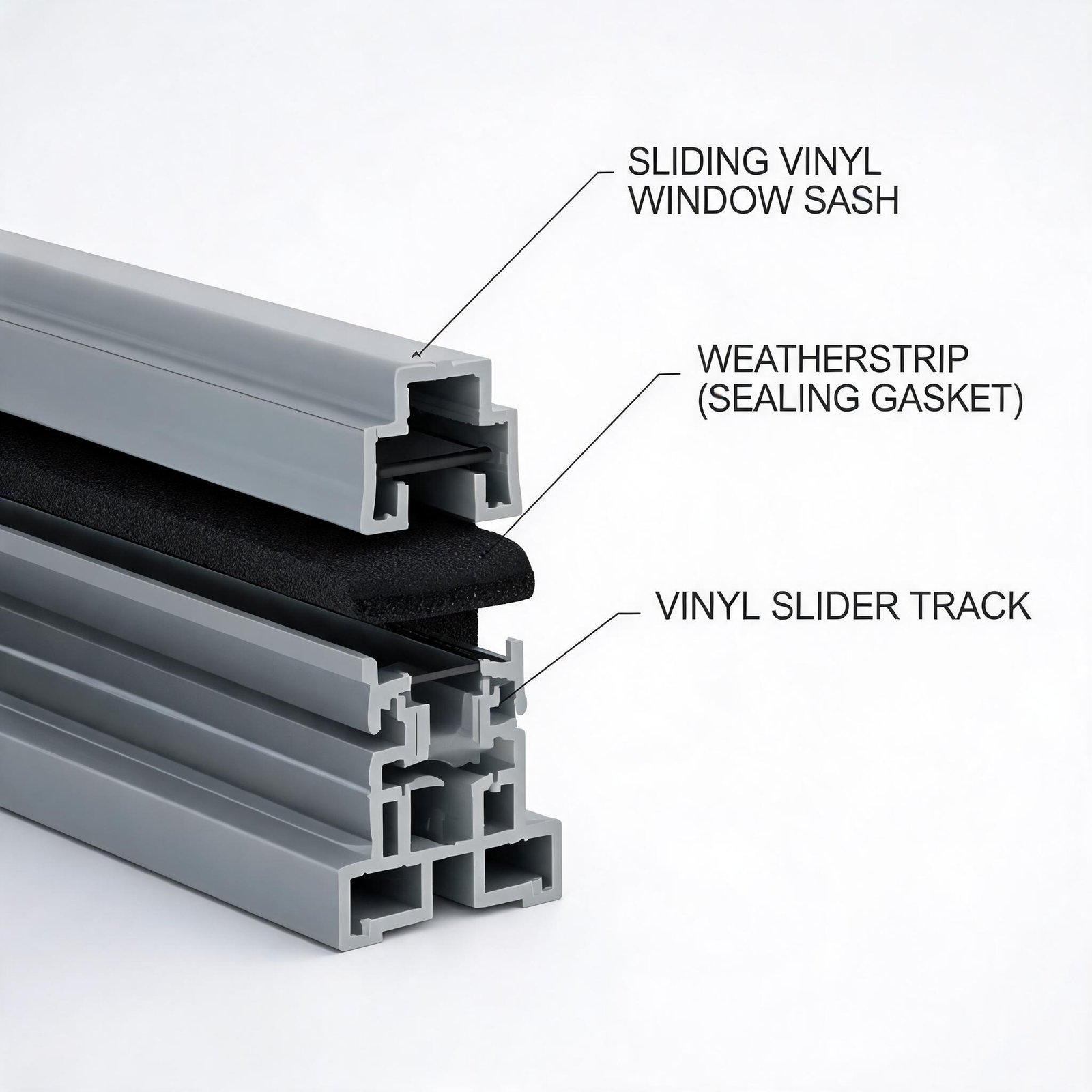
European tilt-turn windows are drainage-plane products by design. Water that enters the exterior portion of the frame is channeled down to the glazing tube at the sill — that is intentional. Your job is to keep the path open while maintaining a properly integrated WRB, sill pan, flashing system, and exterior drainage plane.
- Never caulk the exterior of the glazing tube shut.
- Never let foam or sealant bridge the frame’s drainage channel at the sill.
- Seal every anchor bracket penetration through the WRB individually.
- Extend the sill flashing beyond the jamb flashing so corner transitions have no gaps.
Many European vinyl profiles also use a center gasket that creates a two-part drainage chamber. Drive a fastener through that chamber, and you’ve built a capillary path for water into the living space.
For factory-assembled options that eliminate these field risks, superwindowhouse’s premium vinyl tilt-turn windows come pre-validated for drainage, gaskets, and hardware integration.
Tilt and Turn Adjustment: How to Fix a Sagging Sash
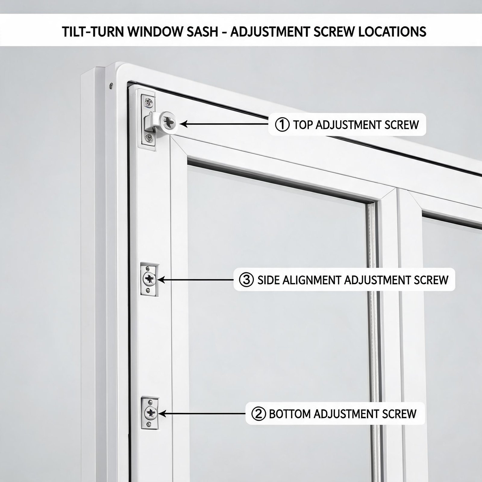
A sagging sash is one of the most common field complaints on tilt-turn windows. The usual culprit is the bottom pivot hinge, although improper frame shimming, loose anchor brackets, opening movement, or insufficient bearing support can produce similar symptoms.
Diagnostic Checks First
- Sash droops in the tilt position and drags when closing → bottom hinge needs vertical adjustment.
- Uneven gap along the lock jamb → scissor arm pressure needs adjustment.
- Sash binds on the top corner of the frame → the scissor arm top pivot needs resetting.
Before adjusting hardware, inspect the reveal around all four sides of the sash, confirm the frame remains square, and check that the anchor brackets and structural blocking are secure. Hardware adjustment cannot permanently correct a distorted frame.
The 4mm Allen Fix
- Move the sash to the tilt position.
- Locate the adjuster screw on the bottom pivot hinge (usually a 4 mm Allen or Torx recess).
- Turn clockwise to raise the sash, counterclockwise to lower it — half-turn increments only.
- Close the sash and re-test tilt and turn functions after every adjustment.
- For scissor arm pressure, find the pressure plate screw at the top edge of the sash and adjust the same way.
Two cautions: always turn the sash vertical before touching the scissor arm, and never force past the mechanism’s end stops. Force a geared mechanism past its stop, and you’ll strip it permanently.
If the sash still sags after adjustment, the cross-blocking has shifted or the anchors are loose. Re-shim and re-secure the frame before touching the hardware again.
Technical Comparison: Anchor Bracket vs. Nailing Fin for Tilt-Turn
Some tilt-turn units ship with fins, but anchor-bracket mounting is the dominant European method, and it changes the engineering rules. The correct mounting method is always the one approved for the specific product, wall assembly, exposure category, and design pressure. Here’s the decision matrix:
| Parameter | Anchor Bracket Mounting | Nailing Fin Mounting |
|---|---|---|
| Load transfer | Point loads through adjustable steel brackets | Linear load along the flange perimeter |
| Cross-blocking required | Yes, at hinge side and lock jamb | Generally not required |
| AAMA 2400 flashing fit | Method B preferred; Method A requires sealing every bracket penetration | Method A is standard |
| Fastener type | Screws only, minimum 1″ framing penetration | Screws, 6D nails, or staples |
| Sash adjustment range | Vertical/horizontal, ±4 mm on most hardware sets | Not applicable — shims only |
| Sash removal after install | Serviceable via hinge release tool | Full frame removal required |
| Hardware serviceability | High — locks, scissor arms, and hinges replaceable | Low — often the whole unit must come out |
| High-wind performance | Excellent when brackets align with structural blocking | Dependent on fastener density |
For a vinyl tilt-turn line targeting DP ratings above 40, anchor brackets with cross-blocking is the only reliable answer.
Common Installation Mistakes That Void Manufacturer Warranties
- Nailing anchor brackets instead of screwing them.
- Driving fasteners through the glazing bead drainage chambers.
- Blocking the glazing tube with foam.
- Installing into an out-of-square opening, which distorts the multi-point lock geometry.
- Skipping the sill pan on water-exposed elevations.
- Using high-expansion foam on the hinge side.
- Ignoring the manufacturer’s cross-blocking diagram.
Each one of these can void the warranty on virtually every major U.S. and European brand. Warranty language varies by manufacturer, so retain installation photos, verify approved materials, and document that the unit was installed according to the current product instructions.
Keep Your Stock Code-Ready for Builders and Wholesalers
The takeaway for builders and procurement teams is simple: a superb installation guide is worthless if the product itself isn’t engineered for the same installation discipline.
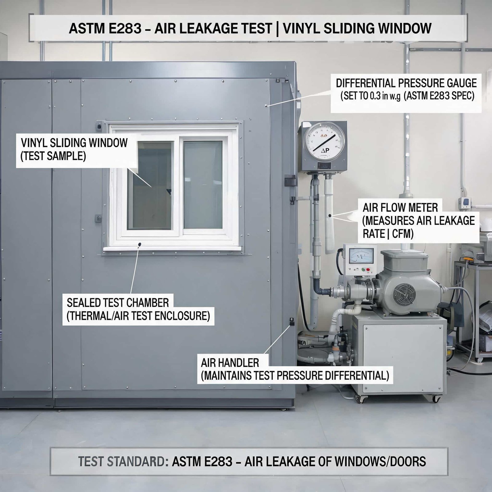
When evaluating a new vinyl window line, confirm the manufacturer publishes explicit tilt and turn adjustment procedures, a documented AAMA installation method, and NFRC-certified U-factor and SHGC data for each glazing package. Cross-check those documents against the actual units, and you’ll avoid the callbacks that erode margins.
Also confirm the applicable design pressure rating, water penetration performance, air infiltration data, structural fastening details, drainage configuration, compatible flashing materials, and replacement hardware availability. These documents help builders compare products accurately across climate zones, wall systems, and project types.
A window distributor that carries factory-documented product lines — including custom aluminum and UPVC window offerings with published flashing and hardware details — is the safest partner for multi-family and custom home programs.
FAQ
Q: Can I use the same flashing method as a nailing-fin window for a tilt-turn unit?
A: Yes — the AAMA installation flashing sequence is similar. The difference is that tilt-turn units need anchor brackets sealed at each penetration and dedicated cross-blocking at the hinge side. Follow the exact window manufacturer’s approved flashing detail when it differs from a general AAMA method.
Q: Why does my tilt and turn window sag after installation?
A: Usually the bottom pivot hinge needs vertical adjustment with the 4 mm Allen screw. If that doesn’t fix it, check shims, cross-blocking, frame squareness, and anchor brackets before touching the hardware again.
Q: Does AAMA 2400 cover retrofit window installation?
A: No. AAMA 2400 applies to new construction in one- and two-family dwellings and townhouses up to three stories. For replacement work, follow the manufacturer’s instructions and consult FMA/AAMA 100 for drainage-method solutions.